As a part of my CAN-bus project on my ’63 Falcon (which will be part of an upcoming multi-article blog), I needed to interface the vehicle speed sensor (VSS) with the MegaSquirt MS3X standalone ECM that controls the 5.0/302 in the Falcon.
The VSS is a “variable reluctor” style sensor that generates an AC sine wave as it is turned. The sensor has a drive gear on the end which meshes with a gear on the output shaft of the transmission. The particular sensor I have is completely electronic. (There is another variation of this sensor that I had employed prior to this project which featured provisions to connect a mechanical speedometer drive cable to the dash. The “crossover” sensor filled the gap between when computerized engines were introduced and the time fully electronic dashes were introduced.)
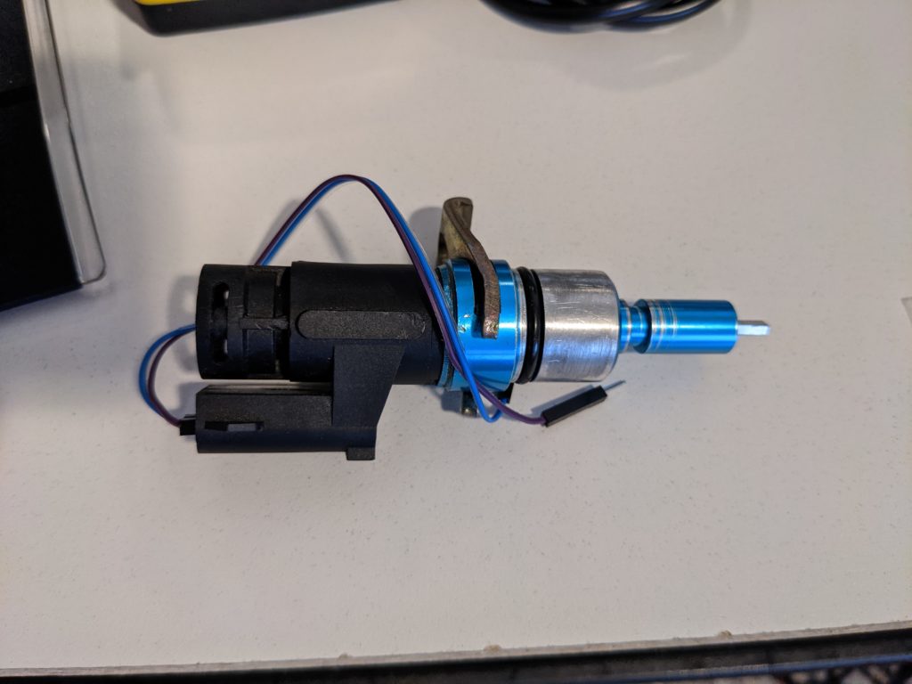
The MS3X has many customizable inputs, so this ECM can be applied to many different engine configurations. The MS3X has a few circuits that can be used to connect the crank and cam position sensors and has internal components to handle the required signal conditioning. However, using these inputs requires using another input port for the VSS. Thankfully, the designers had already made such a port available that can handle a high-frequency input like a VSS. But the output signal from the VSS still needs to be “conditioned” for use by the MS3X’s processor, hence the need for an interface chip.
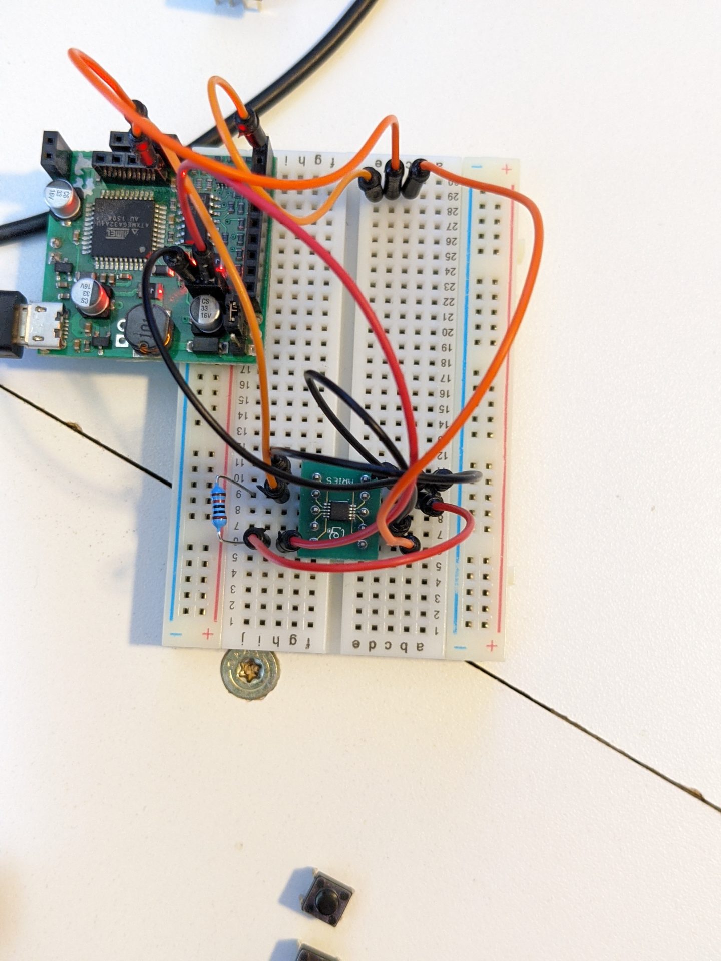
In looking around, I found the answer in a couple of solutions for just this type of signal conditioning – a “Variable Reluctance Sensor Interface”. Both Maxim (with their MAX9924) and ON Semiconductor (with their NCV1124, which has two input channels) have some nice offerings. The MAX9924 is an amazingly small surface mount chip which required me to purchase a special breakout board due to the small footprint of the chip and the leads that come out of the body of the chip.
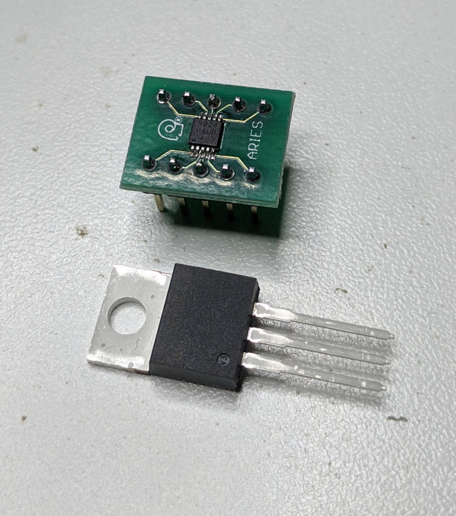
The ON Semiconductor IC chip uses the more traditional SOIC-8 footprint and I was able to use a breakout board that I had on hand.
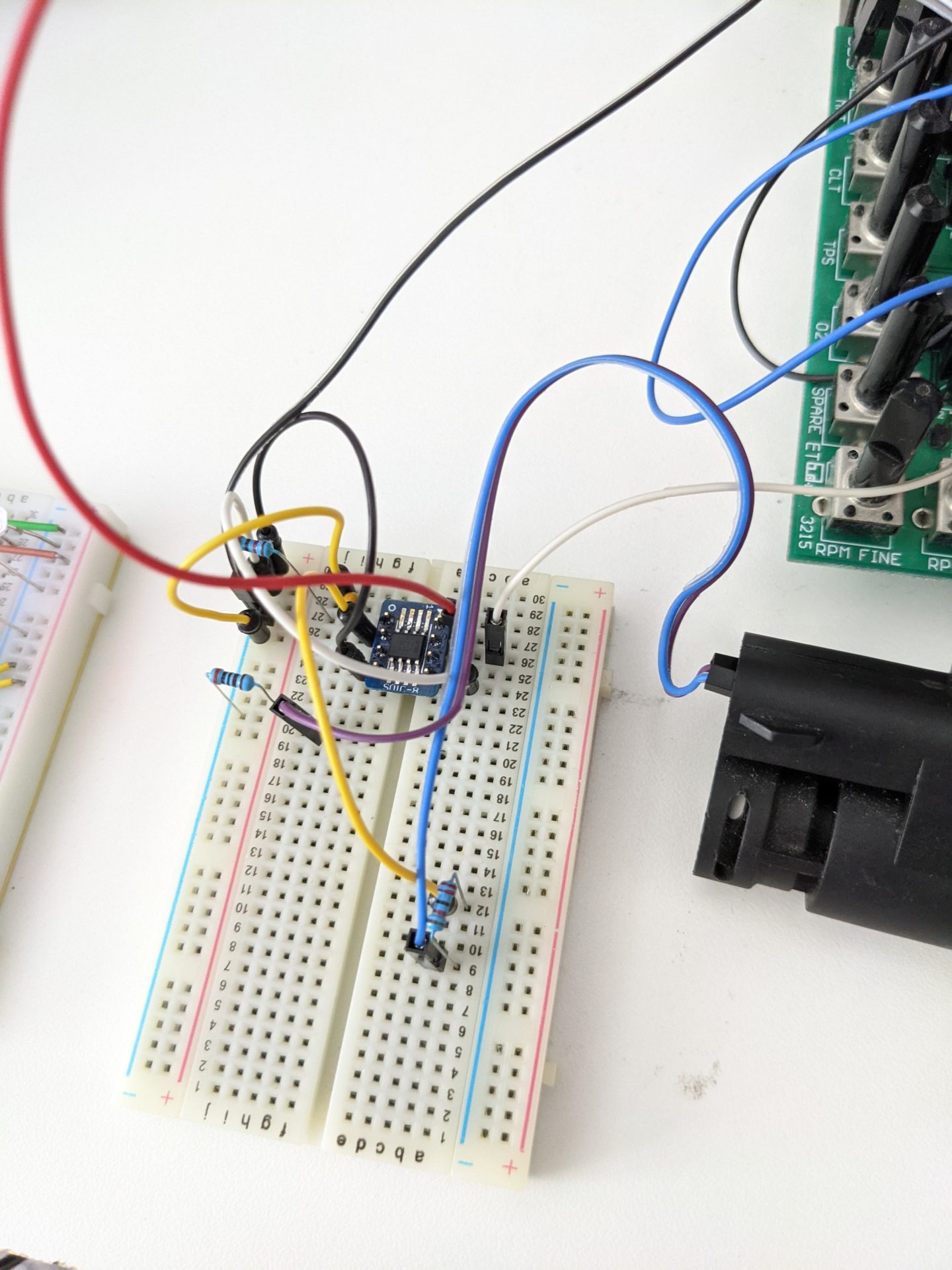
After the initial tests with the signal generator on the o-scope, I decided to do some real-world testing with the actual VSS. I put a cordless drill on the VSS input shaft and gave it a whirl. Below is a video of the waveforms on the Labrador GUI (I’m using the NCV1124 chip here). The Yellow trace is the output of the VSS and the light blue trace is the square wave output of the interface chip. It’s this signal that the MS3X will use.
With the testing confirming proper operation of the chip and the desired output completed, I connected the output of the chip to the “PT4” breakout of the simulator board attached to the MS3X ECM.
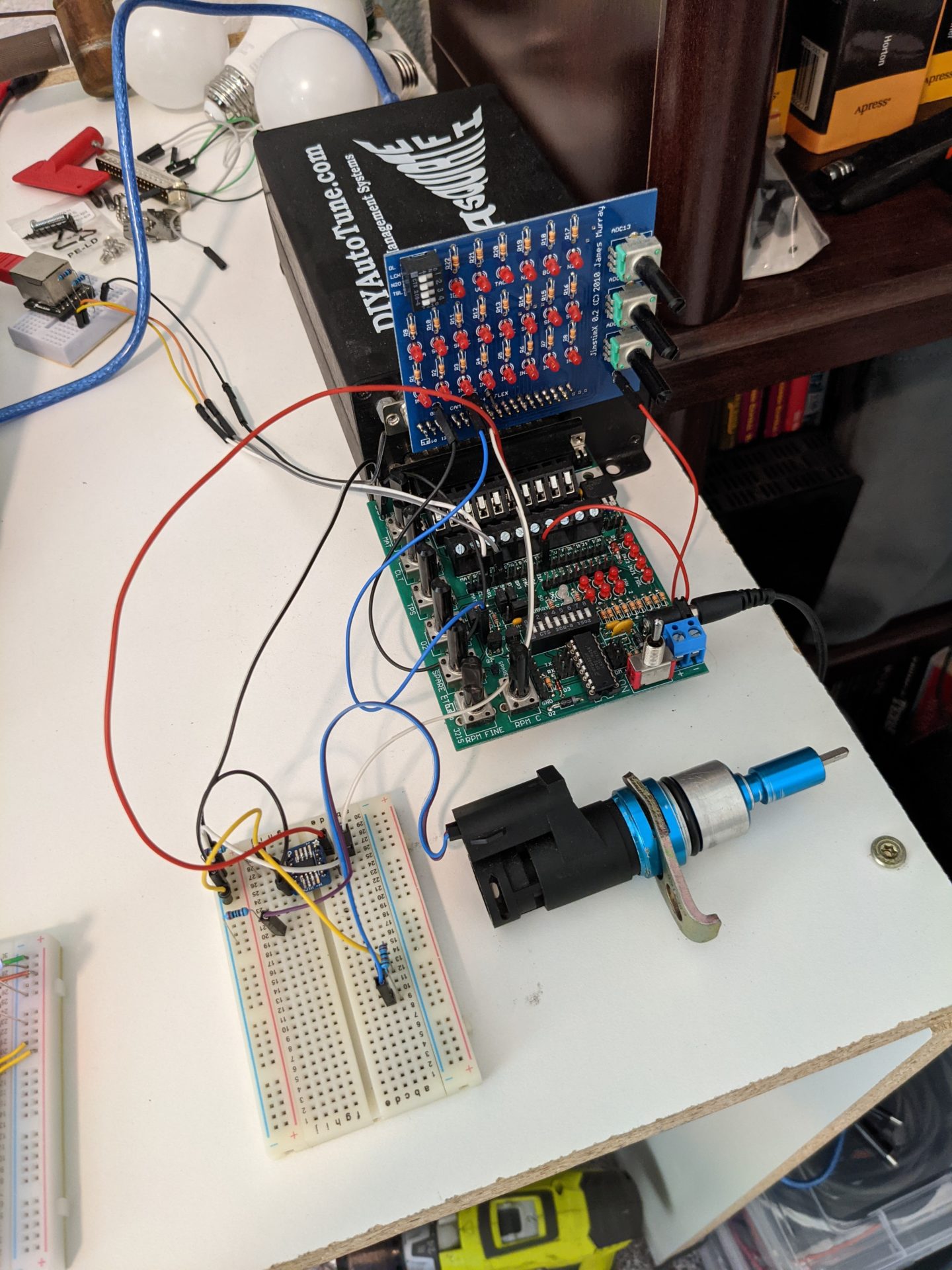
In the TunerStudio tuning software, I went in and set the required parameters for the input, mapped it to the PT4 port and then created a gauge in the TunerStudio dash, mapping it to the PT4 port and setting the gauge properties. I gave the VSS another spin with the cordless drill. The drill was only able to spin the the VSS fast enough to register about 33 MPH, but when I spun it with a Dremel tool, I was able to “peg” the speedometer (the speedo is 2nd gauge from the upper left in the video below).
Now that I have a working speedometer input on the MS3X, the next step will be to set up the speedometer data to be broadcast over the CAN-bus. That exercise will be part of my upcoming blog on the ’63 Falcon CAN-bus project.
You can also subscribe to my Rumble channel “Spitzen-sparkin’ with Electrojammer” to keep up to date with my videos!
As always, THANK YOU for visiting!