
NOTE: The article which you are about to read requires exposure to dangerous levels of electricity! I have spent a lot of years working with not only low levels of DC voltage, but also AC voltages up to 230 volts. ELECTRICITY IS DANGEROUS AND CAN KILL if you do not know what you are doing! If you do not feel comfortable with this kind of activity, please DO NOT engage in it. Call an electrician or someone who has experience working with household (mains) voltages.
Recently, my wife purchased some ceiling fans from an online auction. The merchandise in these auctions are new items, which have been returned for various and sundry reasons including missing parts, damage or they simply do not function at all.
Being the curious, resourceful and crafty individual I am, it’s often possible to find or fashion a replacement part for something lost or damaged. And if it doesn’t work (as in the case of electric/electronic goods)? WELL! That just gives me an excuse to take something apart and study it.
I have always been intrigued by electricity and electronics, dating all the way back to my days in grade school. I had the good fortune of living down the street from a gentleman named Ed Duffin. Ed was an Electrical Engineer who worked for Medtronic, and from what I have been told, he was one of the guys on the design team for the Pacemaker. Ed was a brilliant and personable individual, and some of the neighborhood kids would enlist his help when they got to high school and started taking advanced Mathematics classes (Calc. Trig, etc.).
In the early 80’s, he even helped me build a flasher circuit for a street crossing on my model railroad. Right off the top of his head he was able to come up with a laundry list of things to buy from the local Radio Shack. Once I rounded them up, I was to report back to his place for the build. In less than an hour after my arrival, Ed, with a scrap of wood, some copper wire (for the pos. and neg. rails) the components I rounded up: a few transistors, resistors, capacitors, a couple red LED’s and a venerable 555 timer IC, had built a working representation of a flashing crossing signal! Unfortunately, I’m not sure if I still have it or not, but at some point I plan on digging through my old HO train stuff in boxes to see if has survived all of my moves over the years.
So it was with that same sense of wonder all those years ago that provided me with the inspiration to go rooting around in a wireless control module for a ceiling fan. Upon installing the fan motor, light kit and associated controller, which controlled the fan speed and the on/off/brightness of the light, I was left with a fan that did not work. Making sure I had a good supply of power from the breaker and wall switch, I checked the output of the controller.
Nothing.
I even went so far as to go through the whole “learn” procedure to pair the remote with the controller.
Still nothing!
To rule out that the fan and light were not the culprits (as if my previous troubleshooting didn’t already identify the source of the issue), I hooked the fan and light directly to the wiring from their respective wall switches. I always like to check the integrity/function of the rest of the apparatus, mostly for piece of mind (but sometimes multiple things can fail at the same time, as they did on my ’62 Falcon once upon a time, but that is for another time/post).
Hit the switches. Yep. Got fan. Got lights. Good to go there!
My wife had purchased two fans from auction at the same time. Both were made/distributed by different companies. But by some stroke of luck, they both came with the same exact model of controller and remote. So I took that controller from the other fan and wired it up, so I could at least complete the install of one fan that day (hey, at least my wife was happy to get a fan in her craft room!)
Turn the switch on. Hit the buttons….YAH! We have a winner!
I finished the fan install and turned my attention to the other problematic controller. I was pleased to note that this unit had a couple screws that held the back cover on. Good! There might be some salvation in this after all.
When I removed the cover, I found what appeared to be an overload condition, which had blown off a portion of the copper trace (the copper pathways) for the neutral (return) circuit on the PCB (printed circuit board). Knowing that overloads like this are usually caused by improper initial installation, I inspected the rest of the board and noted no other damaged traces or components. Often times if there are any silicon(-based) components, these can be damaged as well. Sometimes that damage is not readily apparent. Such was the case here as you’ll read about further on….

I placed the board under my Raspberry Pi “microscope” to ascertain the extent of damage. I cut a short piece of brass strip and after cleaning off the trace ends, soldered it in place to bridge the blown-out portion of the trace on the PCB.


In my previous inspection of the board, I had also noted the board had a small fuse. Testing it with the multimeter confirmed that it was blown, so I replaced it with another fuse of the same value (7.5 amp). Now the fun begins!
Using a power cord I had salvaged from an old hand mixer (taking care to keep the 3 output wires of the module from touching anything else or themselves), I wired up the cord to the inputs on the controller and crossed my fingers as I plugged the cord in………….
OK! No spitzen-sparkin or loss of the factory smoke out of the wires or components! That’s half the battle right there!
Using a multimeter set for measuring AC voltage, I checked the output wire for the light and was happy to note that it responded correctly to the on-off commands of the remote. GOOD! The wireless function and associated hardware were still intact and functioning. However, I could not get the motor (fan) output to respond – it just stayed on and would not turn off. I unplugged the power cord and grabbed the multimeter.
This particular device controls fan speed by using three Triacs to route the electricity though one of two resistors (for low and medium speed) or directly to output (bypassing the resistors for high speed) – a fourth Triac on the board controls the light). For the uninitiated, a Triac can be thought of as an”on-off switch” and is basically the AC cousin of the DC MOSFET, which is used to control DC current (if you do a search on MOSFET’s, and Triac’s, you will find TONS of information on them!). Although Triacs may look similar to or the same as a MOSFET (same TO-220 package), they allow current to pass in both directions, where as MOSFET’s only pass current in one direction. As mentioned before, despite the presence of protective devices (i.e a fuse), silicon-based devices are often recipients of these overloads, and they don’t like it! In using the ohmmeter function of the multimeter, I discovered that the Triac that controlled the high-speed fan was shorted, which was not allowing current to be turned off, hence the constant output. For the sake of completeness, I checked the other two Triacs and was pleased (for the moment) to note they were at least not shorted.
I can sometimes be clumsy, and I thought “there must be a better way of checking the outputs than messing with 120V AC and bare wire ends…”. In an “AHA!” moment, I remembered I had an old light fixture in the closet that became redundant when we updated some fixtures several months ago. After desoldering and removing the offending Triac I wired the light fixture up to the motor output of the controller so I could check the low and medium speed fan functions. They both worked as intended, so I hooked the fixture up to the output for the light to check the dimmer function, which also worked the way it was supposed to.

SO….. now that we have done our troubleshooting and systems assessment, let’s take a look at this Triac and see what we can find out about it….
A quick search online using the numbers on the case of the Triac produced a data sheet for it, which would come in handy for sourcing a replacement. The failed Triac was an ST Microelectronics T410-600, logic-level Triac, rated for inductive loads of 4 amps at 600 volts with a gate sensitivity of 10 milliamps. After a bit of scrounging around online, I was able to locate a suitable replacement with the same specs which I could get the next day (I was up against a deadline to get the fan installed in our guest room before visitors arrived later in the week). I wound up procuring a package of WeEn Semiconductor BT136-600E Triacs (hey, I can always use additional parts for future projects!).


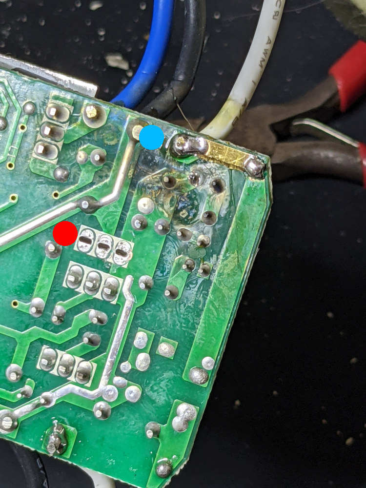
The blue dot in the upper left is the new fuse. The red dot to the right of the fuse shows the location where the new Triac will be installed. The other two Triac’s for fan speed control are to the left. The white dot marks the location of the Triac for the light control. It is mounted to an aluminum heat sink due to the heat generated from the heat caused from PWM-ing the Triac for the dimming feature. The low and med-speed fan resistors are under the heat sink. The short black wire at the bottom is the antenna for the wireless receiver.
The pinouts of the two Triac variants was also the same, so after verifying correct orientation, I soldered the new one in place, hooked the controller back up the the light fixture and power cord, plugged it in and hit the buttons…..
Success!!!
Yeah, I know a lot of you were hoping for loud popping noises, showers of sparks and general mayhem in much the same fashion as with “Nitro”, the submarine electrician in the Kelsey Grammer movie “Down Periscope”, or maybe like YouTube celebrity ElectroBOOM. But as a school teacher once admonished me, “We will have none of that here!”.

After tearing down my testbed, I took the controller up to the guest room and proceeded with the fan install and test, which, much to my relief, went smoothly and without incident, electrical or otherwise.
I’m glad I was able to use the electrical knowledge I have gained over the years to troubleshoot, assess and repair a problem such is this. It kept me from having to spend money for a new controller and it kept an existing piece of electronics out of the waste stream, all for the cost of a few parts and some of my time. I even learned a few things about Triac’s in the process of doing my research, which I will be able to apply to future projects.
Dennis J. Holmes
August, 2021